Building the Atma-Sphere M-60 Mk II
Copyright © 1998, John Harper
Table of Contents
My interest in transformerless (OTL) amplifiers began when a dealer demonstrated the Graaf GM200 to me. I was amazed by its transparency and by its imaging, but unfortunately also by its price. Since I've always had a soft spot for the exotic, I started looking into what else was available at a price that I might be able to afford. I read all that I could find about OTL designs, such as Clive Locke's article in Glass Audio 4/92. By chance I also found on the Web an excellent survey article on OTL technology. While I was doing this, my eye was caught by the advert for AtmaSphere which appears regularly in Glass Audio and elsewhere, showing their brilliantly-styled 6C33C-B based Novacron amplifier.
I quickly discovered that there are few OTL designs which are distributed in Europe, and (as far as I know) no native European products. AtmaSphere does have a couple of distributors over here, but it was not really practical for me to get to them (it would have cost me about a third of the purchase price of the amplifiers!) Although I don't like the idea of buying without having a chance to listen, in the end I decided to take the plunge and build from a kit. This wasn't so much to save money (although, unlike some kits, they are much cheaper than the assembled units), as because I wanted to "get my hands dirty". I've built a few (solid state) electronic gadgets in the past, to my own designs, and I've also done a fair amount of electrical and mechanical soldering in my model train days. To build a kit like this it is absolutely essential to be able to solder well and confidently; this is much more important than understanding how the electronics works.
The limited number of AtmaSphere reviews I was able to find (by Harvey Rosenberg and Art Dudley) were very positive, some orgasmically so. I was very taken by the appearance of the Novacron, rated at 100W, but in the end I decided to go with the M60 Mk II, which is rated at 60W. There were a few reasons for this. First, the M60 is significantly cheaper at $2300 in kit form. Secondly, I had received decidedly mixed views about the 6C33C-B. It is a fabulous piece of tube engineering, but I heard of potential difficulties both with their supply and with getting them well-matched. I also preferred the 6SN7 driver stage of the M60 Mk II to the miniature triodes used in the Novacron.
It took about three weeks for M60 Mk II serial number 234 to reach me after I placed my order, but the last week was spent covering the last couple of miles (delivery can be a problem in the south of France). I was also surprised at how compact the package was. Given what I knew about the size and weight of the finished amplifiers, I was expecting a fair-sized wooden crate. What I actually got was a carton about 20" x 18" x 15". This is thanks to ingenious packaging, where the very substantial chassis parts go around the edges, protecting the delicate parts on the inside. Emptying the box revealed a large plastic bag full of components and smaller hardware, numerous boxes of Sovtek 6AS7G tubes, and buried in styrofoam beads at the bottom four large toroidal transfomers and two conventional ones. Other small boxes contained the smaller tubes - Philips/Sylvania JAN 6SN7GTAs - and the meters.
Everything looked in good shape, although the final stages of construction did reveal a very slight bend in the edge of one of the chassis, which had been at the outside of the box. This was only about 1/20", noticeable when I fixed the bottom cover.
All of the smaller parts, including all electronic components as well as the tube bases and hundreds of nuts, bolts and so on were in one large plastic bag. This is my only quibble with the packaging, since it would make life easier if the larger bits of hardware, the components and the smaller hardware were each in separate bags. As it was, I spent an hour or so sorting them out in this way. This also influenced the way I approached the assembly, since to get rid of the larger parts I did the main mechanical assembly on both chassis before starting the electrical part.
The kit sets out to include absolutely every part needed, even including solder and generous spares of easily-lost tiny nuts and bolts. In the event the only things I ran out of were cable ties. I may have used these more generously than intended, but I like to keep things tidy. I also used a more heat-shrink sleeving than supplied, in a variety of sizes.
The components are of good quality. Resistors appear to be metal oxide for lower powers, with substantial wirewound parts where higher powers are required. (I am intrigued to know where some of these, such as the 43.1KW 10W 1% cathode load resistors, are sourced). The three signal capacitors are all polypropylene (Relcaps), and the driver stage rectifiers are 1N4937 rapid-recovery types. Connectors are gold plated, with Neutrik XLR sockets for the balanced input. The chassis is a substantial pressing, as it needs to be to carry the weight of the transformers, with all holes precision cut. All metalwork is finished in a distinctly retro grey hammertone. My only visual disappointment was the meters, which were rectangular rather than the classy circular ones shown in the advert.
By the end of construction, I had found a single packing error in the kit: a missing binding post for the meter. This was easy to substitute until the part showed up, posted by Atma-Sphere within hours of receiving my e-mail. Packing a kit like this must be a nightmare
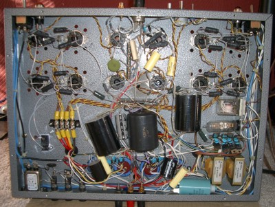
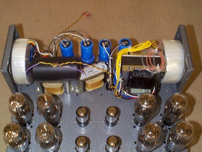
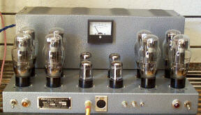
Each finished chassis is large: 17" wide by 13" deep, and 8" high. The under-chassis depth is a bare two inches, which can pose problems if you want to make modifications. It is arranged with the four output stage tubes for each phase on either side, with the four 6SN7 driver tubes in the middle, all in two rows. Behind the tubes is the transformer housing, with the bias adjustment meter in the middle.
The first thing I did was to read the manual from cover to cover. This is very much a "cookbook", with detailed instructions of what to do at each step. All wiring is point-to-point, and the details of component placement and wiring are shown in a couple of diagrams. A schematic is included, but it would be perfectly possible to build the kit without referring to it. In fact, it contains a couple of errors (for example, the decoupling capacitor for the grids of the upper half of the casodes is not shown), and the power supplies are not shown, but these do not affect the construction since the assembly instructions are correct and complete. The instructions are completed by an excellent 10x8 colour photo of the chassis underside whose present sorry condition is a testament to its usefulness.
All AtmaSphere designs use what they call "Balanced Differential Design", which is quite different from the traditional Futterman approach to OTL. The heart of the circuit is a completely symmetrical output stage. This avoids the asymmetry inherent in the Futterman design and its successors. Indeed, I would say that this is even more symmetrical than a complementary transistor amp, since the output devices are identical. The basic design was originally used in the Wiggins Circlotron in the 50s.
The diagram shows the basics of the output stage. In reality, each of V1 and V2 is actually made up of eight parallel triodes (four 6AS7G tubes). Each of the power supplies (shown as B1 and B2) must be fully independent, with its own secondary winding, rectification and smoothing. This is the only real additional complexity of this configuration.
Under quiescent conditions, the currents I1 and I2 flowing in the two halves of the circuit are identical, so no current flows in the load. Resistors R1 and R2 tie the two ends of the load to ground and ensure that they are at the same potential, which will be rather more than the driving voltages E1 and E2, as required to sustain the quiescent current.
Suppose now that E1 rises, and E2 falls by an equal amount. V1 will draw more current, so that I1 is now greater than I2. The current difference flows through the load, while R1 and R2 provide a reference for the cathode follower operation of V1 and V2. (Without R1 and R2 there would be no reference and the operation of the circuit would be unpredictable).
Eventually, as E2 falls, V2 will be cut off. Thereafter, increasing load current is provided only by the increase in I1. A half 6AS7G is rated at 125mA steady state, and can provide up to 300mA or so as a peak meaning that this configuration can source about 2.5A. This should require little or no grid current, but in any case the 6AS7G is designed to handle significant grid current. The top part of what appears to be the anodes, between the top two mica plates, is in fact a pair of radiators for the grids. (This does not apply to its smaller brother the 6AS7GA, which lacks these radiators and therefore should not be used where grid current is required).
Any symmetrical drive can be used to the output stage, but in the M60 the whole amplifier is symmetrical. The input stage consists of a cathode coupled differential pair of cascodes, with a tube constant current source as the shared cathode load. This stage is responsible for all of the voltage gain in the amplifier, about 24.5dB after feedback. This stage , and accounts for three of the four 6SN7s in the driver stage, with one half of one tube remaining unused.
The differential pair is an excellent building block, which is why it is almost universally used in integrated circuits such as op-amps. It has very good rejection of both power supply variation and of common-mode input, and requires no cathode bypass capacitor. Just how good its power supply rejection is became apparent later on, as described below. The M60 accepts either balanced or unbalanced inputs. For unbalanced input, the differential pair is one of the classic phase splitter circuits used in push-pull amplifiers.
The input stage is followed by a driver stage consisting of two identical 6SN7 cathode followers, one for each phase. This is capacitor coupled from the input stage, by the only two capacitors to be found in the signal path.
Three independent B+ supplies are required, one for the driver stage (which also has a B- supply from the same transformer), and one for each phase of the output stage. As supplied these are rather rudimentary, with just a single stage of capacitor smoothing. The output stage capacitors are however a fairly massive 3000m F each, provided by a total of four 1500m F, 150V electrolytics.
Construction for the most part requires the usual tools. For soldering, I used a 50W temperature-controlled iron which I bought for the project. This is definitely worthwhile, since it can provide plenty of heat for the heavier joints. If necessary it can be turned up to a higher temperature for the odd extra-heavy job (for example, the output stage filament wiring). Other essentials are fine-nosed and round-nosed pliers (the latter for bending component leads), wire cutters (a small pair for trimming component leads and a larger pair for heavier cable), and a good selection of smaller screwdrivers,. I including size 0 and 1 Philips (not Pozidriv). Some less obvious tools are:
A digital multimeter is invaluable for checking resistor values, and will be needed during setting up (although an analog meter would be fine for the latter). I use an inexpensive one that cost me about $40 in the local do-it-yourself emporium.
Before actually starting construction, it is a good idea to read throughly what one of the newer books has to say on the subject. My personal favorite is Morgan Jones, but Rozenblit is good as well. Remember as always that tube circuits involve high voltages, up to nearly 800 volts in this case, and should be treated with great caution once they have been switched on. The big smoothing capacitors can hold their charge for hours, ready to give a very nasty shock to the unwary.
The assembly went smoothly if rather slower than indicated in the instructions. It took about twelve hours per chassis, working steadily and with no noteworthy difficulties. Point-to-point wiring is just slow, although satisfying. The fiddliest part is the components in the driver stage. Generally speaking, I followed the instructions and didn't try to improve on them.
The instructions divide the construction into several parts, and recommend that the chassis are built one after the other. The first part is the mechanical assembly of the tube bases, output smoothing capacitors, tagstrips and so on. Here I deviated slightly from the instructions by completing this stage for both chassis, so as to get rid of all the larger parts such as bases from the parts waiting to be assembled.
Next comes the output stage wiring. This involves no components, just lots of wire joining the tubes and power supply. The kit includes a large amount of insulated wire for this, but I had chosen to use silver wire throughout, with Teflon insulation. I bought 10 metres (33 feet) because this qualified for a discount. I never dreamed that I would need more, but in fact I ran out and ended up using a total of about 40 feet. I also used silver-loaded solder, and I must say that I would now never use anything else. Wiring with silver is a real pleasure, quite apart from its alleged sonic qualities. It is much more "live" than copper to handle, and of course solders like a dream. Teflon is also a delight, since it doesn't melt no matter how close it gets to the soldering iron. Since audio is all about aesthetic pleasure, I am not ashamed to say that wiring the output stages was as sensual as listening to the music afterwards.
I did make one change from the instructions at this stage, a minor one but one that I was very happy about later on. The instructions say to concentrate all of the wiring for each phase onto a single output smoothing capacitor, with the other connected by a pair of wires. However I took all of the output wiring (to the tubes and to the output terminals) to the outermost of each phase, and the supply wiring to the innermost, which greatly simplified some later modifications as well as reducing the number of wires that has to be crammed onto a single small terminal.
The next step is to add the filament wiring. For the output tubes, which pull 2.5A each, there is separate wiring from a distribution panel, fed from a toroid with one secondary rated at 19A per phase. Soldering four hefty wires to each of the tags for the distribution strip requires lots and lots of heat; even a 50W iron set to a high temperature calls for patience. The driver stages have a pair of filament windings on their own transformer. The kit includes a total of 40 feet of twisted filament wire, which is plenty.
Next is the construction of the driver stages. This is by far the most fiddly part, since this is where all of the small components go, but it isn't difficult. There are a couple of tags which require a lot of wires on them. It's best when possible to follow the advice in the instructions, which is to lace fix the wires mechanically and solder only when all are in place. However this sometimes isn't practical, and in this case I found that the best way was to attach each wire one by one around the edge of the tag, using the minimum amount of solder, then reflow the whole joint with extra solder when all the wires are in place. That at least is the theory, and when it doesn't work is when the dental probe is useful to open out a hole!
I substituted MIT Infinicaps for the supplied Relcap coupling caps. I cannot say whether these sound better, since I haven't heard the Relcaps, but the general opinion seemed to be that the Infinicaps are better as long as you don't mind waiting longer for them to burn in. I later used the Relcaps as bypasses in the output stage.
The kit includes 0.01m F ceramic bypass caps for the driver stage rectifier diodes. I learned the hard way that it is much easier to fit these on the bench, before connecting the diodes. Using a pair of round-nose pliers I formed the capacitor leads into a close fit on the diode leads close the diode body, crimped them tight then soldered with a quick touch of a hot iron so as not to damage anything.
In the kit version, the choice between balanced and unbalanced input is made by soldering a wire from the inverted pin of the XLR connector to the ground tag of the phono socket. However in the assembled version, an XLR shorting plug is provided to do the same job. If you plan to use both inputs, you should purchase a pair of XLR plugs and assemble them with a wire between pins 1 and 3.
An important change that I made at this stage concerns the ground bus at the rear of the chassis. The instructions say to make a bus using the leads of the smoothing capacitors, across tags 2, 3 and 4 of an 8-way strip which is otherwise unused. Using tags 3, 4 and 5 instead leaves a pair of tags at each end which can be used to assemble a higher-quality rectifier, as described below. I also soldered connections directly to the speaker posts, rather than using tags as in the instructions. It seemed a shame to have silver wire and gold plated posts, then make a joint using inexpensive tinned steel tags. It does however require a hot, powerful iron and a lot of patience to make a good joint to this mass of copper,
There is one error in the instructions here. Steps 3 and 4 concerns the installation of the 600W resistors that give a ground reference to the output stage, as described above. For some reason they say "DO NOT SOLDER at this time" - but nowhere later are these joints soldered, nor does anything seem to depend on their not being soldered at this point. I checked with Atma-Sphere, who told me to go ahead and solder them.
It's worth taking care with the wiring, to make sure that the filament wiring is kept out of the way of the signal wiring as far as possible, especially in the driver stage. Where wires do cross, they should do so at right angles.
Finally comes the AC power wiring, the transformer installation and the power supply. The wire supplied for AC power is pretty hefty, more than it needed to be in my case since I was wiring for European 230V power. The instructions emphasise the importance of taking all AC wiring round the edges of the chassis rather than anywhere close to the driver stage, which is placed at the front in the middle. Installing the transformers is a heavyweight job but straightforward as long as you have a 3/16" Allen wrench (which I didn't). The operating voltage is selected at this stage by wiring the two primaries of each of the three transformers in series (230V) or in parallel (110V) as required.
The output stage power installation is primarily about fitting the rectifiers. The kit comes with generic bridge rectifiers, which I decided to replace with fast-recovery diodes (Motorola MUR1100A). I therefore didn't follow the instructions closely at this point. Instead I used the two spare tags at each end of the ground bus (as described earlier) to fix the AC end of the diodes, taking the other ends to the capacitor terminals. Each of the diodes was fitted with a 0.01m F ceramic bypass before installation. (Despite all this care, the scope shows significant ringing at around 200kHz as the diodes switch, which finds its way through all of the smoothing into the output supplies. I guess this is a good argument for tube rectification).
The last electrical construction step is to install and wire the bias meter. Strangely, this carries no polarity markings, which means that the connections are a gamble. Nothing bad happens if they are wrong; as it turned out, I got one right first time and one wrong, which I had to reverse. I used about 18" of regular power cord (in a tasteful shade of gold, from an old table lamp), so that it would be easy to work on the chassis with the cover removed.
Apart from the early mechanical construction, I built the two chassis in sequence. I was pretty nervous at the first switch-on, especially since I had ordered a Variac which hadn't arrived (and I was in too much of a hurry to wait for it), but there were no problems at all, (apart from the reversed meter connection). The first step is to check all static voltages without the tubes. Then the twelve tubes are inserted, and the really nail-biting switch-on happens. On the first chassis everything worked first time. On the second chassis there was one bad output tube. I realised straight away, because it glowed brightly at one point on the grid even when the chassis was switched off! This was due to the stored charge in the caps. Closer examination of the tube showed that the electrode structure had suffered severe mechanical damage. Since there were several spares in the kit, I simply replaced it. (It has subsequently been the first sacrificial victim in my quest to discover real electrode dimensions for tubes, which are seemingly impossible to obtain).
The output stage adjustments must be made at this point. There are two controls for this, on the front. First, the speaker (or dummy load) must be reconnected using the bias test output. This is a neat idea which avoids having a switch in the signal path. It's important to check that the meters are correctly zeroed with power on, as they are somewhat sensitive to stray magnetic fields. Now, when the output power is switched on, the balance control is adjusted so that the meter reads zero, indicating that there is no DC offset. This is fairly sensitive control but since quite significant DC offset is considered acceptable (e.g. "up to 1V" according to Ben Duncan) it's not worth being too fussy. Then the "bias test" switch is pressed, which disconnects one phase of the output, and the bias control adjusted until (with everything fully heated up) the current indicated is 550mA. This adjustment needs to be repeated from time to time as the tubes age. The controls on the front are fairly vulnerable to accidental changes, so go easy when dusting. It's also important to remember to reconnect the speakers afterwards, otherwise the output is passing through the meters which will do nothing either for the sonics or for the meters.
At this stage I hadn't yet built the pre-amp to go with the Atma-Spheres, so I wired my CD player directly and verified that music was coming out. I then left the first one to burn in for a couple of days with a signal generator and a dummy load (a 10W 100W resistor, a piece of industrial art in itself).
Since I built a pre-amp and went on a two-week vacation between the two chassis, I had to control my impatience to hear some actual music. Eventually I was able to put the complete system together. The pre-amp is a HiFi World KLPP1. This is fed by an elderly Marantz CD50SE (due for replacement) and an even more elderly Audio Research AR-1 deck, consigned to the garage for the last several years until I decided to start listening to vinyl again. Spendor BC1s, also elderly but with no plans for replacement, complete the system, with Kimber 4TC speaker cables and Soniclink Pink interconnect (fairly inexpensive silver-plated OFC coax). I had no idea how "friendly" the BC1s were. I was concerned about this, since the word is that OTLs in general are very fussy about speakers and cables, and Usenet chit-chat suggested that this was equally true for the AtmaSpheres.
In any event the first real test was a great success. With only limited burning in, the sonic quality was excellent. The bass, generally considered a weak point of OTLs, is strong and well-controlled. I suspect this is due to the Circlotron design, and that the reputation is due to the inherent failings of the Futterman topology.
After construction, I was travelling almost continuously but I have now listened to them the M60s for about a hundred hours. What I find extraordinary with these amplifiers is how engaging they make the music. Even when I am not seriously listening and just passing through the room, I find myself drawn in. In some ways the best commentary has been from my wife, who has no interest in audio and prefers to listen to the news station on the radio. She said, "For the first time I'm enjoying listening to recorded music". Not being an audio critic, I can't compare with dozens of other systems, but I can certainly say that I don't regret my choice.
Hum and noise were initially at very low levels. On one channel there was no audible hum, while on the other it was audible a few inches from the speaker. However, over the following weeks the previously-silent channel developed worse and worse hum until it became really intrusive. At this point I started looking around with a scope. I was amazed to find that one of the driver transformer secondaries was open circuit, so that the rectifiers were in effect working as a voltage doubler on half-wave power. The power supply ripple on the driver stage was at around 3V. It says a lot for the balanced topology that it wasn't producing deafening hum in this situation. However the circuit does depend on close tube matching to achieve power supply rejection, and the driver tubes (or half tubes) were clearly drifting apart. I was able to improve the situation slightly by swapping tubes around.
I was even more amazed when I discovered that the other chassis had exactly the same problem, although on the opposite secondary. Atma-Sphere immediately sent me two replacement transformers, although one of these was damaged in transit.
My conclusion at this point was that the amplifier really deserved better power supplies. Ralph Karsten mentioned to me in an e-mail that new amps were now being fitted with choke smoothing. I found the Hammond catalogue on the web , and ordered four of their model 156G chokes from Handmade Electronics who keep a good range. This is a 3 Henry, 40mA choke, ideal for this application. (A larger value might have been better but would not have fitted inside the chassis). I decided at the same time to extend choke smoothing to the output stages, and selected Hammond part 159ZA (300mH at 1A) for this, also ordering four of these.
Over the Christmas break I fitted all of these, together with 47mF Solen polypropylene second-stage smoothing caps (once again selected as being the largest that would fit beneath the chassis). For the output stage supplies the chokes were simply connected between the two smoothing caps for each phase, although I did also fit 2mF bypasses (Solen polypropylene) to the second stage caps and also the 0.1mF Relcaps that came with the kit. (The Harvey Rosenberg review suggests using up to 200mF of paper-in-oil bypass, which I haven't tried).
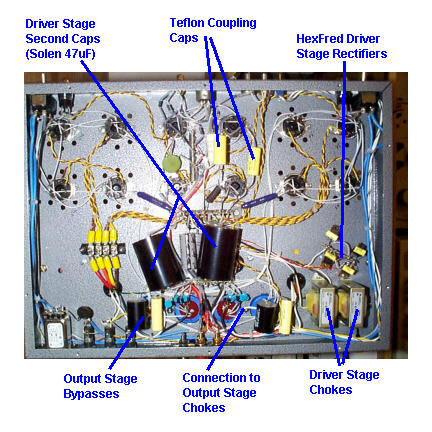
Fitting the chokes to the driver stage was a puzzle, because two extra tags were needed and there weren't any available. I decided to fit the rectifiers on a new tagstrip in an empty part of the chassis (well away from the driver stage itself), meaning that no tags were required for the AC connection and hence freeing the two that I needed. Since I had to change the rectifiers, I replaced them with HexFreds, bypassed with 0.01mF Relcaps. I confess that I do not really know whether polypropylene is better than ceramic in this application, but in any case the scope shows no trace of switching noise.
The chokes have done what was required. There is now no visible ripple on any of the supply lines is now down to a few millivolts. Hum is just audible, ear pressed to the speaker, with a cyclic variation. I suspect that this is related to the low-frequency ripple that CLC pi-filters leave, at the resonant frequency of the final LC stage. (This is something that I have not seen in any textbooks or articles, but it happens both in reality and in Spice. It is not a steady ripple, as seen on the first stage cap, but a sort of random wander within the first stage ripple voltage. If you need a truly rock-steady voltage, then regulation seems to be the only answer).
Fitting the chokes required some metalwork on the chassis. It is obviously not a good idea to do this once the parts and wiring are in place, but if there is no choice then it is essential to avoid leaving swarf which can (and probably will) cause short-circuits later on. I developed the following technique for drilling holes with minimum risk. First, I mark out the hole in the usual way. Next, I roll a "sausage" of Blu-Tak (or similar -- I understand that Blu-Tak is an expensive audio tweak in the US, but in Europe you can buy it anywhere) about 1/4" thick, and lay it in a circle around the marked position, just surrounding the future hole. Now, I drill a pilot hole with the smallest practical drill (1.5mm or 1/16") in a small electric drill, running slowly. The Blu-Tak catches the swarf, and the low speed stops it being thrown around. The Blu-Tak is carefully removed and any escaped swarf picked up. Next, I fix a short length of tube (an offcut of copper pipe is ideal) above and below the pilot hole, with Blu-Tak, and then with a normal electric drill again running slowly, open out the pilot hole to the correct size. The tube again stops the swarf from flying about, After all this, it is still important to check carefully for any tiny pieces of swarf that may have escaped. The risk with point-to-point wiring is less than with a circuit board, since wires and tags are generally further apart.
One problem has been a mechanical buzz from the output stage transformers. Whoever says that toroids don't buzz is welcome to experience mine! Strangely, the transformer that buzzes has changed over time. The problem is significant when both chassis share a power outlet. In this case, switching one chassis on can aggravate the other chassis into producing an unacceptable noise level. For the moment the solution is to run them from different outlets, which in effect separates them by several ohms of power wiring.
Measurements show that the amplifiers give about 24dB of gain, i.e. 17V of output for 1V of (unbalanced) input. This is at a measured output impedance of 10W ,and (corresponding closely with the theoretical figure based on analysing the circuit). The frequency response is flat (within less than 0.1dB) from 30Hz to 20kHz, and down by about 0.5dB at 10 Hz and 40kHz. At 100kHz (the limit of my signal generator) it is down by 1.3dB. The claimed figure is -3dB at 1.5MHz, which I could not achieve, not that it is of much use unless you are trying to build an AM transmitting station. These measurements were made at 1W output into 10W ; measurements made at 30W showed -2.2dB at 100kHz. The measured output impedance is a little over 10W, which again corresponds well with the theoretical figure.
Distortion is entirely second harmonic up to around 10W output (into 10W ), where it reaches my measurements show it reaching -20dB (10%), although this seems very high considering the sound quality. [And in fact this measurement is wrong - see latest news.] Third harmonic is at around -60dB at this power level. Beyond 10W, all harmonics start to rise rapidly. At 1W second harmonic is at -32dB with all others below -60dB.

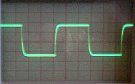
Excess phase shift (i.e. the non-linear phase shift which causes smearing) is non-existent in the range 20Hz - 50kHz. A square-wave input shows a rise time of about 5mS; the spec claims a slew rate for the output stage of 600V/mS, which may well be true but the driver stage never asks for anything like this since the frequency response is rolled off in the input stage.
One very nice thing about dealing with AtmaSphere is the level of support they give. Considering the number of small parts in the kit, one mistake (the missing binding post) seems pretty honorable, but the missing part was sent as soon as I reported it by e-mail. I have also had ongoing discussions with AtmaSphere about the transformer problems and other things, and have always had very rapid and helpful response. They also provide a very good and informative web site, at www.atma-sphere.com. I would rate this kit 9/10 for quality of instructions (10/10 missed only due to the single error), and 8/10 for ease of assembly. AtmaSphere's support warrants 10/10.
The choke smoothing is essential, at least for the driver stage. (I'm still wondering about the effect on the output stage). I would also recommend the rectifier upgrades, and in fact I regret not having used Hexfreds in the output stages as well.
The claimed 60W power output seems distinctly optimistic, and if you really need this kind of power it would be better to use a higher-rated amplifier. However in normal domestic use I can fill my entire house without encountering audible distortion, using old and I believe fairly inefficient speakers.
I see no reason to worry unduly about the alleged OTL problems with cables and the like. The design has low feedback and when the frequency response does roll off, it is due to a single pole at the input stage. There seems to be no basis for instability. On the other hand, the high output impedance (10W or so) could lead to frequency response problems with speakers whose impedance varies widely over the audio bandwidth.
If you are thinking about OTL, stop thinking and buy a pair of M60s. You'll enjoy building them, and you'll enjoy even more listening to them. If you're not thinking about OTL, go and listen to some M60s and see if you don't change your mind.
Valve Amplifiers, Morgan Jones, Newnes 1996, ISBN 0 7506 2337 3.
The Beginner's Guide to Tube Audio Design, Bruce Rozenblit, Amateur Audio Press 1997, ISBN 1 882580 13 3.
High Performance Audio Power Amplifiers, Ben Duncan, Newnes, London, 1996, ISBN 0 7506 2629 1.
Latest News - 31st March 1998
This weekend I finally got around to fitting the Teflon coupling caps (Relcap TFT, from Handmade). It's too early to tell whether they make any difference. I also switched to using "quasi-balanced" interconnect, i.e. balance interconnect from an unbalanced source, with the cold-to-ground connection at the source. The cables are home made, with silver wire, PTFE insulation, and Belden screening (all also from Handmade). I repeated the distortion measurements using my newly acquired HP334A, which gave consistent results with the measurements in the paper. However I still have some doubts and will be repeating the measurements.
Latest News - 3rd May 1998
3.5W |
0.3% |
10W |
0.6% |
20W |
1.7% |
40W |
3.9% |
45W (onset of visible clipping) |
4.7% |
I have now been able to make correct distortion measurements, which are shown in the table. These include a correction for the 0.3% or so distortion that my HP334A distortion analyser shows on the output of the signal generator. It is important, as Ralph pointed out to me, to make the distortion measurement across both terminals without an independent ground - I used a differential scope probe, connected to the analyser. Otherwise the inherent even harmonic cancellation of the circuit is lost, and very high levels of 2nd harmonic result.
At the same time I fitted Ralph's suggested change to the driver stage plate load, reducing it from 30KW to 3KW. This doesn't have much effect on the measured figures, including the onset of clipping, but I haven't had a chance to listen yet and see if it gives the claimed sonic improvement. In fact, the clipping occurs in the input stage because of the limited headroom that V2 has, imposed by the 47V zener on the V3 grids. I have given a lot of thought to improving the input stage, but all possibilities involve major surgery and/or violate the original design goals. At some point I may try increasing the B+ for this stage to around 600V, and increasing the standing current. But that will have to take its turn.
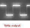
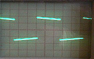
I took some new oscilllograms, to supplement the ones in the body of the article. They are all taken at 10W into 10 W.
 |
 |
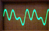 |
Output at 100Hz |
Output at 10kHz |
Distortion residue at 1kHz |
Latest News - 18th April 1999
I started a major upgrade to the amps over Xmas, although so far I have had time to do it for only one chassis. This consists primarily of changing the B+ for the input and driver stages from 280V to 600V, increasing the standing current in the input stage to around 7mA. This dramatically improves the THD figure as measured at the output from this stage, although it seems to make the overall THD figure slightly worse, probably because of a degree of distortion cancellation which was occurring. Distortion cancellation is a controversial subject, since it does nothing at all to improve IMD.
Anyway, the change involved fitting a new driver-stage power transformer (from Sowters), and upgrading various parts. I replaced all of the electrolytics in the front-end power supply with polyprops (630V 100mF from Solen, too huge to go under the chassis). This was not so much capacitor religion as because using electrolytics would mean a series chain for safety at startup, and the polyprops are just simpler.
I also doubled the output smoothing caps, fitting a second bank of 1500mF caps in parallel with the first. A few months back I fitted the mod suggested by Ralph Karsten (on both chassis) of putting a 1W resistor in series with each output tube plate.
Does it all sound wonderfully better? In all honesty, no, but then they were great to begin with. I think the upgraded chassis does sound a bit more solid than the other one, but it's hard to be sure.
![]() Latest
News
- October 2003
Latest
News
- October 2003
It's a long time since I updated this, but there have been some changes in the meantime. In theory the output tubes can provide a greater output current if they are driven into the positive-grid region of operation. This of course results in substantial grid current flowing. The original 6SN7 driver stage can only handle a few milliamps of output grid current, so I decided to try and improve the dynamic range of the amps by using a driver tube with a higher current capability. The obvious tube to use is the 6BX7, designed for driving deflection coils in TV sets and with a maximum plate current of 50mA or more. I've read that Ralph considers this the ideal driver tube, but he is quite correctly constrained by his requirement to use only current-production tubes. In 2000 I made the corresponding changes. They were quite small - the cathode resistor was replaced by a 12kW part, setting the driver current to about 15mA per phase. The plate resistor had been increased as part of the 600V B+ changes, and this had to be replaced with a 10kW part. Initially I used two 10W resistors in parallel, but this led to problems as described below. The V4 plate decoupling capacitor, which I fitted earlier, now had to be a higher-voltage part. A 630V cap would have been huge, so I decided to re-use the 400V parts, originally the B+ smoothing caps. These would be well within rating normally, but would be exposed to a higher voltage during switch-on before V4 started drawing current. To avoid this I built a 300V zener chain around each of them. This has no effect when warmed up, but clamps the voltage at switch-on.
This had little effect on the maximum power output before clipping. The onset of clipping remains at around 18V peak (32W). The trouble is that as soon as the 6AS7 grids go positive, they turn into a sort of electronic black hole. To drive them seriously positive would require another 6AS7 or similar. At the time (bearing in mind that this was three years ago) I did feel that the sound quality was marginally better. I ran into another problem much later on, after I moved to the US. One channel started to hum quite badly. Taking things apart, I discovered that the solder joint at the end of the plate resistors - which happens to be pretty key connection for much of the driver B+ supply - was in poor shape. The heat from the plate resistors had overheated the joint (and some other surrounding components too). Resoldering the joint fixed the problem, but obviously a longer-term fix was required so I used a chassis-mount 25W resistor mounted at the back of the chassis, avoiding the problem for the future.
Incidentally the move to the US fixed the irritating transformer buzz that one chassis had always had, despite Ralph generously supplying a replacement output stage transformer. I had never been able to eliminate this, despite various attempts such as putting a snubber network across the primary. This seemed to confirm my suspicion that the toroidal cores were marginal at 50Hz, and were beginning to saturate. Unfortunately if you are in Europe there isn't much you can reasonably do about this.
I made one other change, which was to fit a power-on delay for the output stage B+. This is in series with the manual switch on the front panel. It consists of an Ameperex 45 sec delay relay, in turn switching the coil of a normal relay since I wasn't sure about the longevity of the Amperex contacts dealing with 1A or so. The Amperex relays do not make a clean contact, but rather spend a half-second or so alternating between open and closed. This in turn makes the switching relay buzz. I'm sure this does no good at all for the life of the contacts, but this would be an easy part to replace if it ever became necessary. I mounted this arrangement on a piece of aluminium angle at the side of the chassis. The secondary relays have 230 VAC coils, which means that the chassis cannot now be rewired to run on 110V (although it would not be a big deal to replace the relays). When I moved to California I just went to Fry's and bought a couple of big (1KVA) autotransformers, which do a fine (and silent) job of running the Atma-Spheres.
The current tube lineup is:
Well-known changes I haven't made, yet anyway, are:
Here are some pictures showing the final, or at least current, stage of things. Click on the pictures for an annotated enlargement.
|
|
|