Kindness to Filaments
A Study of Different Filament Supply Regimes
It is sometimes claimed that tube life can be extended by reducing the thermal shock of switch-on by some kind of "soft start" circuit for the filament (or heater). This note examines different supply regimes and their effect on the warm-up characteristics. It contains both a theoretical model of filament heating and some experimental results which confirm the model.
Three kinds of filament supply are considered:
Ohms’ Law tells us that the power generated by a constant voltage is given by V2/R, where R is the circuit resistance, while the equivalent for a constant current is I2R. In the case of a filament, the resistance is not constant but varies with the temperature. The resistance varies linearly, increasing with increasing temperature. Thus a constant voltage supply will produce maximum power when the filament is cold, decreasing as the filament warms up and the resistance increases, while a constant current supply will show the opposite effect. This explains the familiar switch-on surge with conventional constant-voltage supply.
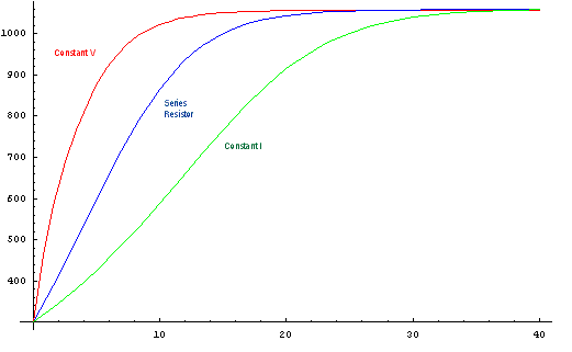
The graph below shows temperature as a function of time for the three kinds of supply. It can be seen that the constant current mode results in much slower warmup, but with no switch-on surge. Arranging a true constant current supply in practice is difficult, requiring a high supply voltage and additional components. The series resistor gives an intermediate effect, but still avoiding the switch-on surge.
The table below shows the warm-up time and peak thermal stress (measured in degrees/sec of temperature change) for the three techniques.
| Constant Voltage | Constant Current | Series Resistor | |
| Warm-up time to 90% of final temperature | 6.7 |
21.6 |
12.6 |
| Warm-up time to 99% of final temperature | 13.3 |
31.6 |
20.4 |
| Max thermal stress (deg/sec) | 156 |
36 |
63 |
Derivation
As the filament temperature increases, the electrical heat input is offset by heat radiation, which increases with the fourth power of absolute temperature (the Stefan-Boltzmann law). Thus at any time the power available for further heating is given by the power input, corresponding to the current filament temperature and hence resistance, and the power loss through radiation. This leads to a differential equation which can be solved numerically for each case. (An algebraic solution is not generally possible and even when possible is too complex to be of much interest). These equations, solved numerically using Mathematica, are the basis for the above figures, with parameters adjusted to give reasonable, lifelike results. For example, the (slightly simplified) equation for constant voltage is:
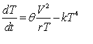 |
where: | T | = filament temperature |
| t | = time | ||
| q | = thermal constant for filament (°K/Joule) | ||
| r | = thermal constant of resistance (W/°K) | ||
| k | = constant parameter of radiated heat (Boltzmann's constant times albido of filament/cathode) |
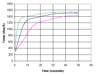
Experimental Results
| The same three configurations were measured
experimentally using a 6SN7, with the result shown to the right. The curves are similar to
those predicted by the theoretical model, with a couple of exceptions. First, the maximum
temperature reached is higher, because this is an indirectly heated tube and the heater
must be hotter than the cathode surface. Secondly, there is a "knee" at
1200-1400° followed by a much slower rise in temperature. I do not know why this occurs,
but most likely it is due to some change in the properties of the insulation
around the heater as it warms up, or maybe of the cathode itself. The experimental configuration measured the voltage and current directly, and used their ratio to determine resistance and hence the current temperature. The different final temperature is due to error in setting the final current rather than any physical phenomenon. |
 |
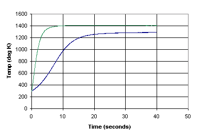
| The second figure shows the same experiment repeated using a directly heated tube, specifically a 300B. Only constant-voltage and constant-current modes were measured, and once again the slight difference in final temperature is due to errors in the experimental configuration. It should be noted that the "knee" is not present in this case, tending to confirm the belief that this results from something specific to the construction of the indirectly heated tube. |
 |
Observations
Use of a constant-current supply reduces the peak thermal stress on the filament by about a factor of five, but increases the warm-up time by a factor of about 3.5. It is awkward to arrange in practice. The compromise of using a series resistor equal to the hot filament resistance, and a constant voltage supply of double that required for the filament itself, gives satisfactory results. Thermal stress is reduced by a factor of about 2.5, while warm-up time is doubled. For example, for a 6SN7 (6.3V, filament current 100 mA) a 12.6V supply could be used with a 10.5
W resistor. (Exact values are not critical as long as the final voltage delivered to the hot filament is correct. It should also be borne in mind that tubes were designed for ± 10% supply voltage variation).A practical approach to the whole problem is to use a regulated heater supply, using a typical semiconductor regulator such as the LM317. If a correctly-rated part (e.g. 1A) is used, the built-in current limiting will cause initial operation in constant current mode followed by continued operation at constant voltage once the resistance increases to a sufficient value. Of course there are people who believe that such regulation of the heater voltage somehow harms the sonic properties of the amplifier. This may well be true for a directly heated tube (due to interaction between the voltage drop caused by the signal flowing in the filament, and the regulator). It's pretty hard to believe for an indirectly heated tube.
The reduced thermal stress may increase tube life (although see below), but it may also reduce it. Unless the B+ supply has a delay, the period while the cathode is warming up will result in operation in saturated mode, where the plate current is equal to the emitted current and there is no space-charge of electrons surrounding the cathode. It is widely believed that this contributes to a phenomenon known as "cathode stripping", where the oxide coating on the cathode is damaged by impact from positively-charged ions resulting from high-energy collisions between electrons and residual gas molecules.
Whether all this is of any practical value is open to debate. By the 1950s, lifetime was a predominant concern of tube designers and industrial users, and if switch-on surges would significantly reduce lifetime then this would be reflected in the literature of the time, which it is not. There could conceivably be some benefit with directly-heated filamentary tubes, whose filaments are more mechanically fragile. The high-end audio world is full of mystical beliefs, and very probably this is one of them.
15th April 2004. Copyright © 2004, John Harper.